LED Cyclone Game
I am working on the LED Cyclone Game. I am utilizing an addressable neopixel strip, an arduino uno board, and a push button. This project reminisces on games that would appear in the arcade.
| Engineer | School | Area of Interest | Grade |
|---|---|---|---|
| Fahmida Aupho | Midwood | Computer Science | Graduated |
Final Milestone
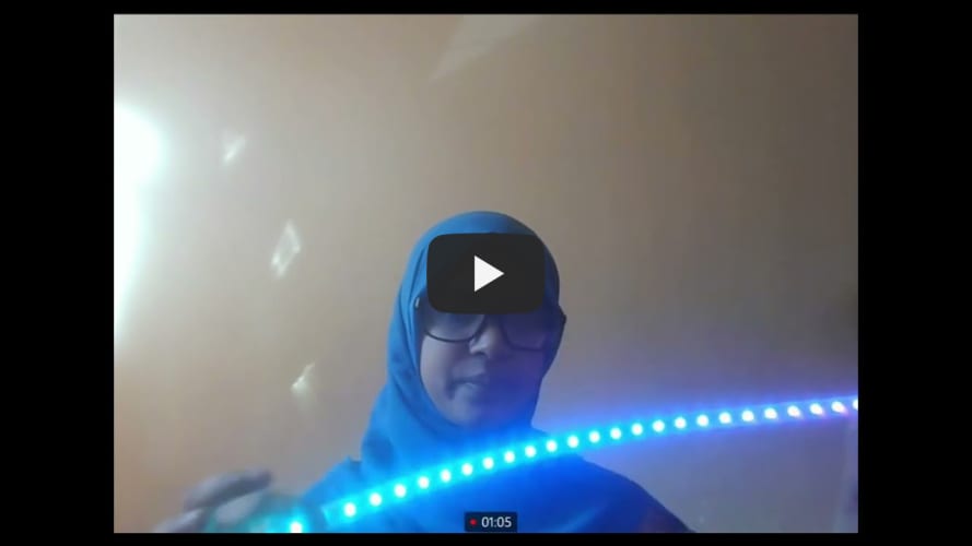
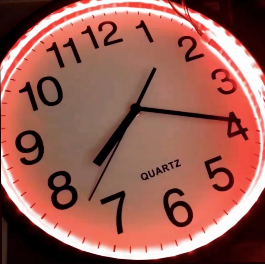
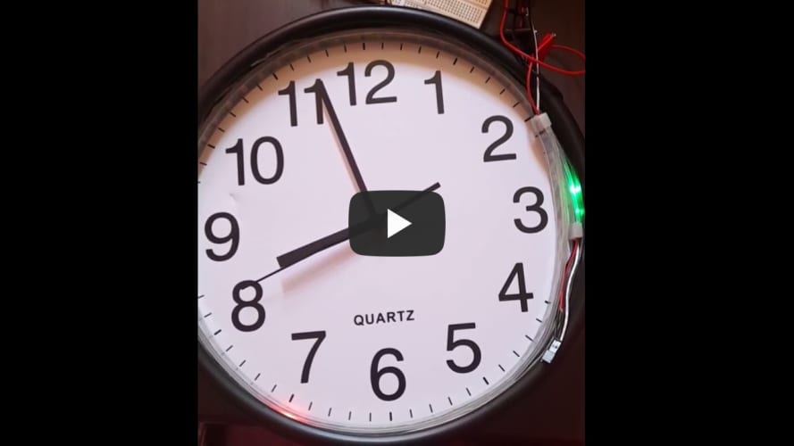
My final milestone is adding my LED cyclone game to a circular frame. I chose a 13 x 13 inch clock and used double sided tape to attach the addressable LED strip to the inside of the frame. I realized that my neopixel was longer than the circumference of the frame so I layered the ends of the neopixel on top of each other. To make further improvements on this game, I will add a battery to the back of the clock. I can also have each hand of the clock be assigned a color on the neopixel.
Second Milestone
My second milestone was to create the cyclone game using the neopixel and a mini push button. The objective of the game is to push the button when the cycling light reaches the designated LED. The difficulty level rises when successful attempts are made. A mini push button has two pairs of legs that are internally connected; the button will complete a circuit once it is pressed. It can be either placed on a breadboard or a printed circuit board. I placed the button in the middle of a breadboard and connected one leg to the 5V volt supply, one leg to the ground pin, and one leg to digital pin 8. I placed a pull-up resistor on the same leg of the button that is connected to digital pin 8. The resistor will prevent the LED from blinking chaotically.
First Milestone
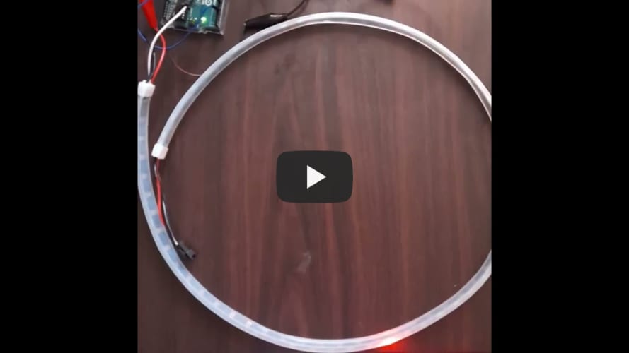
My first milestone was to light up the neopixel. The interface of the neopixel composes of the positive wire voltage, negative wire ground, and data wire. A diode is controlled by an integrated circuit that gains information and changes to data to manage the light. This data is then passed on to the next diode; it is an ongoing process. To power my neopixel I used alligator clips to connect the ground circuit of the LED strip to the ground pin on the arduino. I also used alligator clips to connect the voltage circuit of the LED circuit to the pin 5V on the arduino. Then I used a jumper wire to connect the data wire to digital pin 5 on the arduino uno board. Lastly, I opened up the Arduino IDE to upload the operation “ColorPalette”.